

Construction Techniques
Reading Component Values
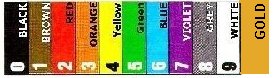
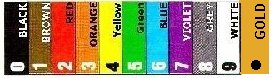
9C1 Recall the resistor colour code, colours 0 to 9 with gold as multiplier.
Recall silver (10%) and gold (5%) as tolerance bands. Identify the value of a resistor between 1Ω and 9MΩ from the E12 series.
Recall how to read both 4 band and 5 band resistors.
Note: The resistor colour code will be provided and actual encoding
or decoding of colours will be either 4 band or 5 band
resistors.
Candidates are not expected to know the values of the E12 series.
![]() Students do not ignore this section as currently
( since November 2004 ) the syllabus has the identification of the value
of a resistor as a question on the exam paper. There is
no easy way to learn this but practice at the use of the code
and a full understanding of how to discern the value from the
rings becomes second nature to you means an easy mark. IMPORTANT
the last question in the exam may be on this topic.
Students do not ignore this section as currently
( since November 2004 ) the syllabus has the identification of the value
of a resistor as a question on the exam paper. There is
no easy way to learn this but practice at the use of the code
and a full understanding of how to discern the value from the
rings becomes second nature to you means an easy mark. IMPORTANT
the last question in the exam may be on this topic.
Colour code rings
It is possible to work out what is the value of a resistor from its coloured rings on its body.
For the exam you only have to understand and be able to recall colour code for resistors with 3 value bands and a 4th band know as the tolerance band.
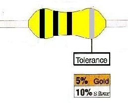
Tolerance Band Silver or Gold colour only
Let us first deal with the tolerance band. This is either a silver band to indicate plus or minus 10% of the value or a gold band to indicate plus or minus 5% of the value.
Value code bands (or rings)
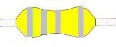
The three code bands (or they can be called code rings) tend to be grouped together in a set of three with the tolerance band set a little to one end - they are only grey in the example below to indicate the location of the bands.
You can tell if you have the resistor round the correct way as there is no silver or gold as a first band.
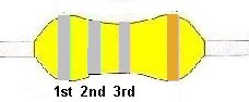
Reading the bands
With the gold (or silver) band on the right hand side the other three bands are "read" just like a book from left to right.
1st and 2nd band
These two bands give you single digit numeric values by reference to their colour from the colour list below.
1st Band
The first number cannot be a 0 so cannot ever be a BLACK band so must be from 1 to 9 (BROWN through to WHITE)
2nd Band
The 2nd band can be any number 0 to 9 (BLACK through to WHITE).
1st and 2nd band give you the first two digits
The first two number you workout from the colours of the first two bands are the actual digits and these digits remain as determined from the colour.
3rd band
This is the band that gives students the most problem to understand.
The band can be any of the colours given below.
Ignore the GOLD colour for the moment as that is a bit special. Note all the colours are the same as for the first two bands so there is nothing new in the number that the colours represents.
The difference with this 3rd band is the way its number is used. You have to think of this not in terms of a number digit as for the first two bands but as to how many 0's (zeros) are added after the first two digits.
If the 3 band is BLACK
If the band is BLACK in colour then it means no 0 (no zero) is added after the first two digits and the first two digits are the value of the resistor.
Thus RED RED BLACK is 2 2 and no 0's ( no zeros) thus answer is 22 ohms
If the band is BROWN in colour then it means one 0 ( zero) is added after the first two digits to make up the value of the resistor.
Thus RED RED BROWN is 2 2 and 0 thus 220 ohms
If the band is RED in colour then it means two 0 ( zero) are added after the first two digits to make up the value of the resistor.
Thus RED RED RED is 2 2 and 00 thus 2200 ohms
If the band is ORANGE in colour then it means three 0 ( zero) are added after the first two digits to make up the value of the resistor.
Thus RED RED ORANGE is 2 2 and 000 thus 22000 ohms
It is hopes that the picture is starting to fall into place and so jumping along a bit:-
if the band is GREEN in colour then it means five 0 (zero) are added after the first two digits to make up the value of the resistor.
Thus RED RED GREEN is 2 2 and 00000 thus 2200000 ohms
3rd Band can be GOLD  by 10
by 10
You will note that no figures are on the gold band. This is a special band and means divide the value of the first two digits by 10 - or put it another way put a decimal point between them.
So you could remember the gold like we show below with a big decimal point on it.
If the 3rd band is GOLD in colour then it means divide the first two digits by 10.
Thus RED RED GOLD is 2 2 divided by 10 thus answer is 2.2 ohms NOTE the decimal point
Thus RED BLACK GOLD is 2 0 divided by 10 thus answer is 2.0 ohms NOTE the decimal point or you could just write 2 ohms
There are several more examples given below the colour code chart. The chart itself is intended to bring together all the points mentioned above.
Note: For this 3rd band there is no association with the meaning of the gold in the 4th band (tolerance band).
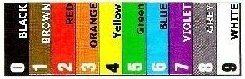
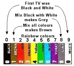
Learning the colours
There are several ways to try to help you remember the order of the colours but you may have already seen that the colours RED to VIOLET numbers 2 to 7 and follow the same order as the colours of the rainbow. BLACK is zero and the top colour is WHITE 9 so you might like to think of the first TV's which were BLACK & WHITE - GREY is a mixture of BLACK and WHITE and is number 8 - BROWN is a mixture of all the colours and is number 1.
These colours representing the numbers are the same for all three bands with GOLD the extra one in the third band - with the possibility of silver and gold as the last band.
Practice writing down the colour and number order so that it is second nature to you.

Please note:- 7 is given as VIOLET but is often called PURPLE
At the side of the colours above is a little rhythm that may help you to remember the order but also many of the colours are in the same orders as the colours of the rainbow !!!
Another little rhythm that some might find easy to remember if you are of "Drinking Age" - Bad Beer Rots Our Young Guts But Vodka Goes Well. It is left to you to work out how this fits but order of the numbers is 0 1 2 3 4 5 6 7 8 9 starting with Bad = Black.
The Rings
The first and second rings are used as the number digit but the third indicates the number of "0's" to be added and the tolerance indicate either 5% or 10%.
So for example if we have a resistor as follows :-
| Example 1 | 1st | 2nd | 3rd | Tolerance |
| Yellow | Purple | Red | Gold | |
| 1st digit | 2nd digit | number of zeros | ||
| 4 | 7 | 00 | 5% | |
| Total = 4700 ohms at 5% tolerance | ||||
| Example 2 | 1st | 2nd | 3rd | Tolerance |
| Grey | Red | Green | Silver | |
| 1st digit | 2nd digit | Number of zeros | ||
| 8 | 2 | 00000 | 10% | |
| Total = 8,200,000 = 8M2 10% (8.2 Meg Ohms) | ||||
With having to be able to read the code from 1 ohm to 9 Meg the difficult part is the early numbers 1 2 3 4 5 6 7 8 & 9 as the 10x must be the gold which is the 0.1 but let us look at 10 ohms to start with:-
| Example 3 | ||||
| What are the colours for 10 ohms 5% ? | ||||
| 1 | 0 | 5% | ||
| 1st digit | 2nd digit | Number of zeros | Tolerance | |
| 1 | 0 | none | ||
| Brown | Black | Black | Gold | |
| Example 4 | ||||
| What are the colours for 1 ohms 5% ? | ||||
| 1st digit | 2nd digit | Number of zeros | Tolerance | |
| 1 | 0 | x 0.1 (divide by 10) | 5% | |
| Brown | Black | Gold | Gold | |
| Example 5 | ||||
| What are the colours for 2 ohms 5% ? | ||||
| 1st digit | 2nd digit | Number of zeros | Tolerance | |
| 2 | 0 | x0.1 (divide by 10) | 5% | |
| Red | Black | Gold | Gold | |
| Example 6 | ||||
| What are the colours for 39 ohms 10% ? | ||||
| 3 | 9 | 10% | ||
| 1st digit | 2nd digit | Number of zeros | Tolerance | |
| 3 | 9 | 0 | 10% | |
| Orange | White | Black | Silver | |
Can you work out what the colour code is for 4, 5, 6, 7, 8, and 9 ohms at both 5% and 10% tolerance?
So for those of you who have not been able to understand the information in the box above here is another way of looking at it :-
The first digit is represented by the first coloured ring
the second digit is represented by the second coloured ring
the third digit or multiplier is represented by the third coloured ring
If we want to know the colours of the rings for 1 ohm of 5% you might think it is Brown Black Black which is wrong. WHY?
| First ring | Second ring | Third ring | Tolerance | Result | |
| Colour | Brown | Black | Black | Gold | |
| Value | 1 | 0 | no zeros | 5% | 10 = 10 ohms |
| Colour |
Brown |
Black |
Gold |
Gold |
|
| Value |
1 |
0 |
x 0.1 |
5% |
|
| 10 divided by 10 = 1.0 ohms or just 1 ohm | |||||
NOTE: The gold is only use in the third digit ring and tolerance ring never in the first digit ring or in the second digit ring.
With practice this exercise will become easy but without practice it will remain a mystery !!!
![]() Resistors and power
capability
Resistors and power
capability
One item that does not seem to be covered in the syllabus but must be taken into account, with carrying out amateur radio construction, when dealing with resistor, is not only their value in terms of resistance ohms but also the amount of heat that they can dissipate when working in a circuit. Else where you have learned about the equation P = V x I, where P = Power and is measured in watts.
You must use the equation to assess the required power capability of a resistor or in other words how many watts of heat can it dissipate safely. Small resistors are only say 1/8 W but physically larger ones can handle say 50 W.
![]() You do not have to learn this... What is E12 ?
You do not have to learn this... What is E12 ?
The E12 series of resistors is a group of what is called "preferred" values. This means that there are not resistors for every single value from 1 Ω to 9M Ω but only a selected few, in fact the highest value in the series is 8M2 (or 8.2Meg or 8200000 Ω)
|
E12 Resistor chart |
|||||||||||
| 10 | 12 | 15 | 18 | 22 | 27 | 33 | 39 | 47 | 56 | 68 | 82 |
| 100 | 120 | 150 | 180 | 220 | 270 | 330 | 390 | 470 | 560 | 680 | 820 |
| 1000 | 1200 | 1500 | 1800 | 2200 | 2700 | ||||||
| 10000 | 12000 | 15000 | 18000 | 22000 | |||||||
| 100000 | 120000 | 150000 | 180000 | ||||||||
| 1000000 | 1200000 | 1500000 | |||||||||
Can you fill in where there are blanks???
Recall how to read components with a numeric marking of the format 4R7, 3k3 or for capacitors, 103.
A resistor with a value marked as 4R7 is 4.7 ohms. The R means it is resistance. The whole number to the left of the R is a whole number of ohms. The number to the right of the R is a decimal value of 0.7 Ohms. We add them together to get the 4.7 ohms value. In the same way 2M2 would be 2.2 Megohms, or 3k3 is 3300 ohms. The R is the actual ohm value, the k for 1000 where 3k3 really means 3.3 x 1000 ohms and M is for a million hence 2M2 really means 2.2 million ohms but we say megohms. 2M2 = 2,200,000 ohms.
A capacitor marked as 103 has a value of .....? Well, it is a bit similar to the resistor code but without using colours where 1 is the 1st digit, 0 is the second digit and the 3 is the multiplier value, so putting them together similar to resistors, we have 1 0 000 which is 10,000 picoFarads or 10 nanoFarads whichever notation you wish to use. They are just equivalent ratings.
Similarly a capacitor may have stamped on it 56n which means 56 nanoFarads. Another might have 10µ which would mean 10 microFarads. Sometimes the F is missing but it is just implied.
Construction
9D1 Recall that screening with thin metal sheet is effective in reducing unwanted radiation from equipment and/or between stages within equipment.
Using metal plate for screening helps us keep wanted signals in their place. For instance,a metal can over an IF transformer will electonically and to some extent mechanically isolate that transformer from the rest of the components. It prevents the IF signal "escaping" into the other components which could cause spurii in your receiver or your transmitter. It also prevents that transformer from picking up signals from other components that could cause instability in the IF and later stages after amplification.
Metal shielding and enclosing of valves and oscillator circuits helps to prevent signals getting in or escaping and also gives some temperature stability.
Metal shielding of your transmitter (A commercial one will probably be in a metal case) will also help prevent the powerful signal from your antenna getting back into the components causing instability and what is called "feedback".
Soldering
9E1 Understand that soldering is a method of joining metal wires and components using solder and a hot soldering iron.
What ever you may be told by others or even overhear soldering does not stick together electrical components.
However soldering does have a similarity to electric arc welding. In electric welding two items are mechanically and electrically bonded together and so to are they in soldering by the use of HEAT and an alloy of metals called SOLDER.
Solder is an alloy of tin 60% and lead 40% is the most popular solder for electronic applications. Its low melting range makes it ideal for delicate work.
Soldering is the word given to action of using solder to act as what might be thought of as the "glue" that when melted bonds the metal wire of components and also links them to the PCB (Printed Circuit Board). In fact the solder is not a glue in the true sense of the word as the hot solder bonds with the component wire and the PCB and thus making a good electrical connection.
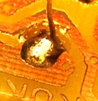
When a solder joint is made well is has a certain "shine" to it where as a poor one looks dull may have an uneven surface or may not have even properly "wetted" the materials to be linked and merely stayed as a great "blob". The wetting has nothing to do with water (in fact you do not want water anywhere near your soldering) but is the coating of the metal to be joined so that the two become one and this is also called "tinning". It is useful to tin multi stranded wires prior to making a joint to ensure that the joint will be a good one with solder right though the wires.
9E2 Recall that solder is a low melting point alloy and that many solders contain a flux to help the solder to flow and to prevent a layer of oxide forming on the surfaces to be joined.
![]() The flux in the solder is not a glue - it does not
in itself bond the components to the PCB but is rather like soap
which aids the cleaning of your hands when you wash them - it
cleans the oxides of the components and the PCB and also helps
to make the solder flow better. With this in mind read on.
The flux in the solder is not a glue - it does not
in itself bond the components to the PCB but is rather like soap
which aids the cleaning of your hands when you wash them - it
cleans the oxides of the components and the PCB and also helps
to make the solder flow better. With this in mind read on.
The solder used for electronics is one that contains a flux within the actual solder core. The effect of the flux is to allow the solder to flow better and also with the heat of the soldering iron removes the layer of oxide that often forms on copper especially which would prevent a good joint being made.
The location where copper is found is on the printed circuit board or PCB. Initially a PCB is a fibre glass board to which a thin sheet of copper has been attached by a adhesive which remains intact even with some heat applied (but excessive heat can cause the copper to lift). The design of the board is applied to the surface with a etch resist material and the board is then placed in a etch tank to remove those parts of the copper that are not required. After etching the copper sections remaining on the board are call tracks where they are linking one joint area to another and the joint area is called a "pad". it is though the pads that small holes are drilled holes into which components are placed.
9E3 Recall that some metals are easier to solder than others.
Easy to solder - copper, brass, tin, gold, and silver
The metals that you will normally encounter in electronics are copper, brass, tin, gold and silver. All of these metals are easy to solder using the normal electronic solder and inbuilt flux. By easy to solder it is meant that a joint can be formed with the solder flowing well and bonding to the materials.
Difficult to solder - Aluminium
Trying to solder aluminium, that is a different matter entirely. It cannot be soldered with the usual electronic solder and can be considered as a material that cannot be readily jointed to others.
When joining a wire to a terminal on a Printed circuit board there is a need to make a particularly good neat joint and this can only be achieved if the wire to be joined has the outer cover cut off and the conduction wires (if not a solid wire) twisted together and then tinned. The tinning make the cable act as a single inductor and ease the problem of achieving a neat joint.
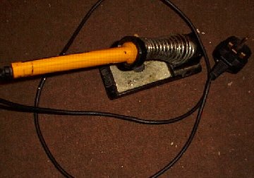
9E4 Understand that the tip of the soldering iron has to be cleaned to help remove any oxide and then tinned to prevent the oxide re-forming and to improve the conduction of heat to the joint.
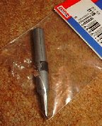
Mention has been made of oxide forming on the components to be jointed. The oxide can also form on the tip of the soldering iron. The tip where the joining takes place is a location which must also be kept clean and this is achieved by wiping the "hot" tip on a suitably dampened sponge and applying a small amount of solder to the tip, what might be described as "tinning the tip" just as was mentioned about the wire above and this also makes the tip shine bright due to the presence of the solder.
The effect of the tinning is to place a thin layer of molten solder on the tip of the iron so that when it is brought into contact with the materials to be joined that the molten solder makes very good contact with the materials and thus allows rapid heat transfer to enable a good joint to be made.
Recall the reason for tinning wires prior to soldering.
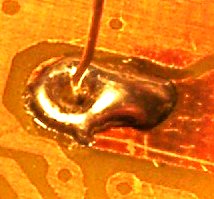
Some components do not like becoming hot and thus a good solder joint must be made very quickly. Normally you would expect to make a joint in less than 2 seconds. A poor joint that is made which leave some solder on one component and some on another and some on the PCB rather than all items being linked together is called a "dry solder" joint. The photo shows a badly made joint.
Recognise components
For this course you have to be able to recognise certain components which are given below.
| Components name | Component picture | Unit | Circuit diagram |
| Fixed resistor |

|
Ohm |
|
| A resistor of fixed value, it comes in many different packages depending upon the power handling ie the amount of watts of heat it can dissipate safely in its normal function. | |||
|
Variable resistor also know as a Potentiometer |

|
Ohm |
|
| A resistor of variable value and intended to be varied by the user. | |||
| Preset variable resistor |

|
Ohm |
|
| A resistor of variable value not intended to be varied by the user except when making adjustments to parts of a circuit that once adjusted remain untouched for most of the time- and a skeleton package shown. | |||
| Fixed capacitor |

|
Farad |
|
| A capacitor of relatively small fixed value which can come in many different packages. | |||
| Variable capacitor |

|
Farad |
|
| A capacitor of variable value and intended to be varied by the user - can be of various sizes depending upon the voltage potential that will be applied to the plates before flashover!!!. | |||
| Preset variable capacitor |
|
Farad |

|
| A capacitor of variable value not intended to be varied by the user except when making adjustments to parts of a circuit that once adjusted remain untouched for most of the time. Also called a trimming capacitor. | |||
| Electrolytic |

|
Farad |
|
| A fixed value capacitor of large and very large
capacitance, also know as a polarised capacitor.
A smaller cased polarised capacitor is called a tantalum capacitor - also polarised. | |||
| Inductor |

|
Henry |
|
| Basically a coil of wire (most often used when forming tuned circuits). | |||
| Inductor iron cored |

|
Henry |
|
| The amount of inductance can be varied such as when adjusting a tuned circuit | |||
| Transformer |

|
| |
| Basically two coils of wire in relatively close proximity to each other so that the magnetic field in one can induce one in the other. | |||
| Diode |

|

| |
| A semi conductor which only allows current to pass in one direction. | |||
| Light emitting diode (LED) |  |
| |
| A semi conductor which only allows current to pass in one direction but illuminates due to the passing current. | |||
| Transistors |

|

| |
| These come in a variety of packages depending upon the current that they are to pass. It is important to be aware of the external connections Emitter Base and Collector as they are not similar on transistor to another. Data sheets are available to indicate package type and what is called "pin out" configuration. | |||
| Integrated circuits |

|
||
| Usually found in a "many legged" plastic packaging and are several semi conductors all together in one package where some examples only need few other components to complete an operational circuit. | |||
| Crystals |

|
Hertz |
|
| Crystals come in many different cases but all perform the same basic function to provide a fixed frequency for an oscillator. | |||
| Microphones |

|
| |
| Microphones come in many different shapes and sizes the one shown is a small electret microphone such as may be used in a desk mic. | |||
| Loudspeaker |

|
| |
| Speakers come in many different sizes according to the frequency range and power they are to handle. | |||
And these are the other circuit symbols you need to know in this course.
| Description | Unit | Symbol |
| Cell | Volts |
|
|
Switch s.p.s.t. = single pole single throw, this is the standard on / off switch |
|
|
| Battery | Volts |
|
|
Switch d.p.s.t. = double pole single throw - this is a switch that can switch two separate lines at the same time. |

|
|
| Fuse | Amps |
|
| Antenna |
|
|
| Lamp | Watts |
|
| Earth |
|
|
| Earphone |
| |
| Chassis |
|
|
| Variable capacitance diode |
| |
| Field Effect transistor FET |
|
The origin of some of the text on this page is from the RSGB with additions by the web master