4e.3 Recall that a filter is a device that blocks some
frequencies and passes others.
Understand the effects of low pass, band pass and high
pass filters. Interpret their frequency/amplitude diagrams.
Understand that a low pass filter and a band pass filter
can minimise the radiation of harmonics.
Transmitters can produce unwanted signals even when care has been taken with
their design. If these unwanted signals are radiated strongly enough to cause
interference to RF users one or more filters is needed to eliminate or at
least reduce the level of the unwanted signals. The filter needs to be designed
to pass as much of the wanted signals as possible.
There are three filter you need to be familiar with for this course:-
-
Low Pass
-
High Pass
-
Band Pass
for the purpose of this course the filters are constructed from inductors
(L) and capacitors (C) and hence are referred to as LC filters. The
filter is in fact a "tuned circuit"
Filters can be described as passing some frequencies and stopping other hence
the expressions "pass band" and "stop band". In a perfect world the filter
would:-
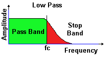
The frequency where the pass band and stop band meet up is called the "cut-off
frequency" (fc) of the filter.
A low pass filter (LPF) passes frequencies lower than the cut off
frequency
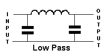
A low pass filter (LPF) is designed so that it passes frequencies that are
lower than that of the stop band so in effect signals above the cut-off frequency
(fc) are reduced. The Low Pass Filter is therefore use with a radio transmitter
to reduce as far as possible harmonics of the transmitted frequency.
In the next animation a plot of the harmonics is overlayed the output frequency
to show how the fundamental frequency is hardly affected by the low pass
filter but the harmonics 2 through to 5 show significant reductions in output
level (amplitude).

You will be pleased to learn that many VHF and UHF transceivers have a low
pass filter built in.
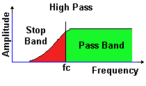
A high pass filter (HPF) passes frequencies higher than the cut off
frequency
A high pass filter (HPF) is designed so that it passes frequencies that are
higher than that of the stop band so in effect signals below the cut-off
frequency (fc) are reduced.

A band pass filter (BPF) passes frequencies between the cut off
frequencies
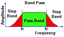
A band pass filter (BPF) is a combination of low pass and high pass filter
that will passes a range of frequencies in the pass band, any frequencies
above or below this range are reduced. Unlike the LPF and the HPF, the BPF
has two stop bands and two cut-off frequencies (fc) at the meeting points
of each of the stop and pass band.

Remembering which circuit diagram refers to which can be a daunting task
for some students. So try to remember just one and the other should then
fall into place.
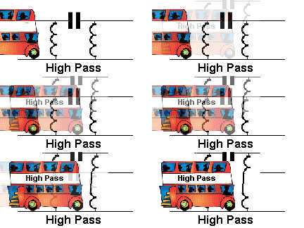 
Think of the inductors at the side of the filter as springs on a lifting
bridge that can operate to allow a high bus to go through the HIGH PASS filter.
Then look at the low pass filter and the capacitors could be like bricks
of a low bridge that cannot stretch and so will not allow the bus through.
Note: That the use of filters on all external leads from a transmitter
can on occasions reduce harmonics from a transmitter.
4e.4 Recall and understand that too fast a rise and
fall time of the transmitted RF envelope of a CW transmitter may cause excessive
bandwidth and that this can be minimised by suitable filters in the keying
stage.
When a morse key is opened and closed to operate a CW Tx too fast a rise
and fall time of the transmitted RF envelope of a CW transmitter may cause
excessive bandwidth a problem known as key clicks. The clicks are a large
number of audio frequencies caused by the sharp edge of the wave form shown
below in RED.
Key clicks can be minimised by suitable filters in the keying stage.
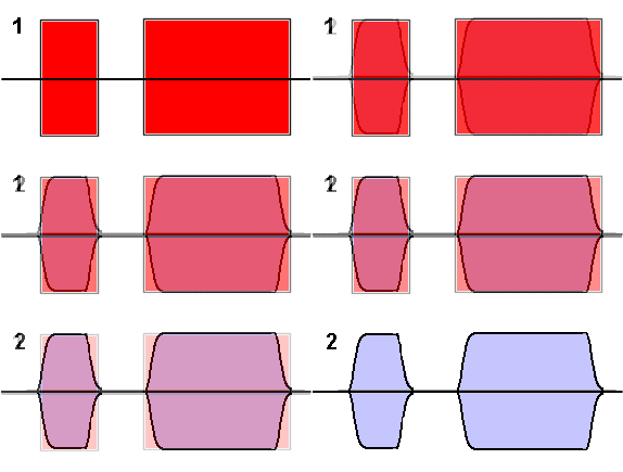 
Note : In the red diagram the very sharp corners to the shape which cause
key clicks whilst in the blue diagram the corners have been rubbed off giving
slower rise and fall times and reduces / eliminates key clicks.
The animation merely show the change from the original to the improved wave
shape.
|