


9A1 Recall the purpose of a multimeter and understand how to set the meter to the correct range and polarity before connecting to the circuit.
There are two types of multimeter :-
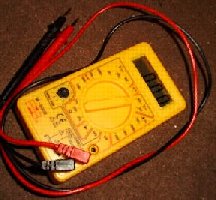
Digital
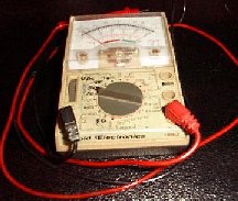
Analogue
Both the meters can carry out much the same function for measuring Volts, Amps Ohms and each has a range of scales.
There are two considerations to make before taking a reading:-
What am I trying to measure?
What sort of reading do I expect?
The first item should be straightforward else you would not even be using the meter but the second is often misjudged. To avoid the risk of damage to the meter it is always worth while starting at the highest setting of Amps, Volts and Ohms and then work down to a level that gives you a reading that you considered in within the range you had expected.
Analogue meters need correct polarity to meter else can be damaged
It is more important to properly observe polarity of the meter connection in an analogue meter and to connect the wrong way round will mean that the needle is driven hard against the zero end stop. If this occurs then there is also the likelihood of mechanical damage to the meter rendering it useless.
Digital meter need correct polarity to meter else misleading reading result
With a digital meter on the other hand it often copes well and merely displays a minus sign to show the wrong polarity but still give you the reading required.
9A2 Understand that voltmeters have a high internal resistance so that they draw minimal current from the circuit under test.
Understand that ammeters have a low internal resistance so that they minimise the voltage loss to the circuit under test.
Understand that a voltmeter is always connected in parallel with a component or circuit being tested.
Understand that an ammeter is always connected in series with a component or circuit being tested.
Measuring Voltages
The measurement of a voltage is trying to assess the potential difference between two places, across a load, and can therefore this can be carried out without breaking the circuit. It is using the meter in parallel with the circuit when the switch is closed. The voltmeter has little or no effect on the circuit being measured due to its own very high internal resistance.
Measuring Current
When it comes to measuring current the only way to do this with a multimeter is to break the circuit at the point of interest and connect the meter in series with the part of circuit if interest, with the switch closed. You could even measure across the switch !! The ammeter has very little internal resistance so it has little or no effect on the current being measured.
9A3 Understand the advantages and disadvantages of analogue and digital displays, and be able to read analogue and digital values.
Whilst both meters can do the same measurements each has advantages that are reflected in disadvantages in the other type of meter.
Digital meter advantages
Simple to read and usually more accurate reading given as the digital display shows the unit and decimal of the unit on many occasions.
Digital meter disadvantages
The Digital meter on the other hand, due to its style of operation does not know, when readings are changing, which value to display nor can it display the rate of change of readings.
Analogue meter advantages
Where there are changes in reading to be determined then the swing of the needle on the analogue ;meter shows the changes and the rate of the change.
Analogue meter disadvantages
The analogue meter by contrast suffered from errors of parallax where you can miss read due to not looking at the meter from right above. Usually there is a mirror behind the scale so that you can see if you are properly lined up. If you can see a reflection of the needle then you are to one side or the other when there is no reflection seen then the reading would be true.
9A5 Understand the use of voltmeters and ammeters to determine the power applied to a circuit.
When you have a series circuit (where all the components are linked one to the next) at all points, with the switch closed, the measurement of current would give you the same answer, or even across the switch itself with the switch open.
With regard to voltage the only time a similar answer would appear is when you were measuring the voltage across components which themselves are connected in parallel. In this case the meter is a voltmeter.
If you want to determine the total current flowing in a circuit however complex then the ammeter must be put in the circuit in a position where all the current in the circuit is flowing. The best place is as close to the source of the current as it enters or leaves the circuit as the same reading would be made.
Would ammeters at A1, A2, A3 all read the same ? NO
A1 and A3 would as they are respectively measuring the current entering and leaving the circuit but A2 is only measuring the current through resistors R1 and R3.
Where could you put a volt meter to measure the voltage in the whole circuit ?
The only place to put the volt meter which is in parallel with the whole circuit is across the input +12V and 0V as shown below.
By the use of measuring voltage and current in a circuit and applying it to the power triangle P = V x I you learned in the FLC you can calculate the power in the circuit.
9B1 Recall that decibels are a logarithm of power ratio.
The Decibel is a unit used to measure the intensity of a sound or the power level of a signal by comparing it with a given level of signal using the logarithmic scale. Note that the log scale is NOT equidistant between numbers as in the linear scale.

Now let's put that into a more understandable English !!
The Decibel is not a unit of anything. It is a RATIO.
It compares the value of one number to the value of another.
Recall that a power gain of 3dB equates to doubling the power and 10dB equates to a power increase of times 10.
Please recognise these equations as you may need to calculate with them later. They will be provided in your exam and you can use a scientific calculator. We will take you through it all slowly.

This is the equation used to
calculate gain of Yagi over a dipole hence the "d" after dB

This
equation is used to calculate the Gain of a Yagi over an Isotropic antenna hence
the "i"

This
equation is used relating to decibel power ratios which could be "W" watts or "m"
milli watts.

This
equation is used for relating Voltages hence dBV as given in
the syllabus above but that on the equation sheet it is just
dB ( not dBV )
So what is dBW, dBm and dBV ?
dBW is associated with power in Watts
dBm stands for decibel (power) in milliwatts
dBV associated wth Volts.
A gain or loss of 3dB is a factor of 2 so 20W with a gain of 3dB results in 40W
out and vice verse a loss of 3dB on 20 W gave a result of 10W.
10W with a 10db gain would become 100 W and 10W with a 10dB loss
would give just 1 W.
This holds true for all dB measurements whether dBw dBm dBV so
if this is the case why do we need to use log10.
Well most of the time you do not need to use log tables nor a
log calculator just so long as you have the basis of dB in
your head as shown above.
As dB may be added together and also subtracted one from
another a Positive Result give a gain a Negative Result give a
loss.
Calculate the power gain or loss of various dB ratios based on 3 and 10dB and their multiples. This includes examples such as 25W is equivalent to 14dBW.
Recall that dB gains and losses in a system can be added to find the total gain or loss in the system.
The equations are :-

When assessing the sound level strength of an audio signal this is how loud it seems to be when heard by the human ear. If someone thinks that a sound level has doubled when power from a audio amplifier is raised from 5 to 10 watts that same person should also consider that a signal would also be twice as loud if the power increased from 200 to 400 watts. The human ear has what is called a "logarithmic" response to changes in audio levels. It is this basis that is used for the "relative" power level given the name of "the decibel" (dB). One decibel is 1/10th of a bel the unit of sound coined by Alexandra Graham Bell.
The number of decibels in relation to the ratio of power levels is given by :-
When using the V1 / V2 voltage equation the the impedance must be the same for both voltages, thus a power amplifier cannot be properly assessed if only taken on input and output voltages, unless those voltage have the same value of impedance in the circuit.
These equations look very complex but in the
scientific calculator sections it is shown how the equations can be
used when P1 = PowerOut and P2 = PowerIn.
Similarly V1 = VoltsOut and V2 = VoltsIn

The log to the base 10 is the usual log used by engineers and would be that on the scientific calculator. The 10 in front of "log" means multiply the log of the ratio P1/P2 by 10, the resulting answer will be the relative power expressed in dBW or decibel watts.
![]()
When the decibel value (dB) and one power value is known then the unknown power can be calculated from the equation at the left.
We are using log to the base 10 as shown by "log10" the 10 to the right of the word log indicate base 10. For clarity we will now omit that 10 and only write "log".
When a question is set and Powerin is not shown then assume that it is 1 Watt.
Example: What is a measured power of 400W expressed in dBW ?
dBW = 10 log(power in watts)
dBW = 10 log(400) = 26dBW Click here to see the calculator key strokes
Example: What is a measured power of 12dBW expressed in Watts ?
Power(Watts) = antilog dBW/10
Power(Watts) = antilog 12/10 16 Watts Click here to see the calculator key strokes
Example: What is a measured power of 25W expressed in dBW ?
dBW = 10 log(power in watts)
dBW = 10 log(25) = 14dBW
Are we correct? Use your calculator to check we have this right.
There is another equation that is given in the equation listing.
![]()
This is used to determine the gain of a yagi over a dipole using the power from each.
Recall (or determine) the power gain or loss of various dB
ratios based on ± 3, 6, 9, 12, 15 and 10, 20, 30dB. (This includes examples
such as 25W ![]() 20 - 6 =14dBW.)
20 - 6 =14dBW.)
Power gain - always a + but often assumed, with no plus sign.
| dB | Calculation | Gain (Rounded figures) |
| +3 | antilog 3/10 | x 2 |
| +6 | antilog 6/10 | x 4 |
| +9 | antilog 9/10 | x 7.94 |
| +10 | antilog 10/10 | x 10 |
| +12 | antilog 12/10 | x 15.8 |
| +15 | antilog 15/10 | x 31.6 |
| +20 | antilog 20/10 | x 100 |
| +30 | antilog 30/10 | x 1000 |
Power loss, always a minus sign in front of the dB number.
| dB | Calculation | Loss (Rounded figures) |
| -3 | antilog 3/10 | ÷ 2 |
| -6 | antilog 6/10 | ÷ 4 |
| -9 | antilog 9/10 | ÷ 7.94 |
| -10 | antilog 3/10 | ÷ 10 |
| -12 | antilog 12/10 | ÷ 15.8 |
| -15 | antilog 15/10 | ÷ 31.6 |
| -20 | antilog 20/10 | ÷ 100 |
| -30 | antilog 30/10 | ÷ 1000 |
See from the tables the answer is in dB but it does matter whether or not it is a gain or loss.
Here is a working question for you:
The sort of question you might be asked is:-
Your transmitter has a power output of 20dBW and the feeder has a loss of 3dB, the antenna has a forward gain of 9dB. What is your ERP in watts (effective radiated power) ?
Solution 20dBW - 3dBW + 9dBW = 26dBW
Now we know that Power(Watts) = antilog dBW/10
so Power(Watts) = antilog 26/10 = 398W rounded up = 400W Click here to see the calculator key strokes
Recall the meaning of:
So what is dBW, dBi and dBd ? From above as these are not a unit of anything what do they mean. The part to look at is the W i and d.
The origin of some of the text on this page is from the RSGB and with additions by the web master