|
|||||||||||||
|
|
|
||||||||||||
|
|
|||||||||||||
|
Syllabus Sections:- Power Amplifiers 3F2 23 Understand the need for linear amplification and identify which forms of modulation require a linear amplifier. Firstly what is linear amplification? We are not
talking about an add on Amplifier but the part of the
transceiver which increase the power of the modulated signal
to the output power required say up to 100 watts. Linear amplification takes the input signal and duplicates it exactly and provides an output that may be several times or even hundreds of times larger than the input power. Which modulations require linear amplification ? AM and SSB Because of the nature of the wave forms both AM and SSB have the amplitude of the wave form at input directly related to the amplitude of the wave form at the output. If the input wave form is not replicated perfectly at the output and so is distorted on output so will be the audio signal received by the distant station be distorted. The distortion could be so severe that it creates harmonics of the input signal which fall outside the desired band width and your signal could therefore fall outside the amateur bands causing interference. Which modulation does NOT require linear amplification ? FM and CW As the FM signal has no amplitude component part which as shown above can causes distortion, and it is only the FREQUENCY that is changing there is NO NEED for a linear amplifier. CW is just on off keying of the carrier again with no change in amplitude there is NO NEED for a linear amplifier. Identify simple RF transmitter PA circuits. Understand the meaning of linearity as applied to a circuit or amplifier You need to
look in The meaning
of Linearity as applied to a circuit or amplifier refers to
the ability of a circuit or amplifier to give an output
signal that is directly proportional to an input signal so
you get out exactly what you put in only amplified. Understand how distortion of a single frequency signal can produce harmonics of that frequency. Firstly
a harmonic is a waveform whose frequency is a multiple of the
fundamental .e.g. x2, x3, x4 etc. So distortion of a single frequency occurs in a device when the output is not a linear function of the input. This Distortion of a single frequency occurs when that frequency, called the fundamental frequency, creates harmonic of the fundamental frequency, and produces what are called second harmonic or third etc which distort the output signal. This frequency distortion due to harmonics is always a possibility in amplifier circuits containing reactive elements such as capacitance or inductance. Understand how distortion of two (or more) frequencies can produce harmonics and intermodulation products of the input frequencies. Firstly
what is intermodulation ? The frequencies of Intermodulation
are mathematically related to the original transmitter
frequencies. Specifically, they consist of sums and
differences of the original frequencies, If
you combine two or more frequencies (sine waves of different
frequencies), then you can get intermodulation products. For
example, make a signal consisting of a 1 kHz (f1) and a 200
Hz (f2) tone: BUT
we also have 1kHz - 200Hz giving 800 Hz Thus the two frequencies
with intermodulation create even more frequencies !!!
----------------------------------------------------------------------------------------------------------- 3F3 23 Recall the function of the main components of a PA circuit, i.e. collector load, bias, input circuit, output filter and matching. Well first we need to consider the design a simple Transistor Amplifier and then break it down into its component parts. Take a look at the
diagram It has all the parts needed collector load, bias, input circuit, output filter and matching. Collector
load, This is at
a basic level any components attached to the output side
of the collector, in Bias On the example shown in fig 7.19 the component RFC1 (RF choke ) is the mechanism to enable the transistor to be biased off as it is connected to Ground and thus makes the transistor operate in Class C, note: in other types of circuits a potential divider ( 2 resistors one connected to the HT rail in the diagram 12 to 24V and the other resistor connected to Ground both linked to the base connection ) may be used to bias a transistor. Input circuit This is
part of the circuit to the left of the base section of the
transistor, in Output filter and matching Again in
the the -----------------------------------------------------------------------------------------------------------
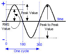
3F4 23 Understand the implications for PA rating of different types of modulation and the effects of speech processing, with particular regard to peak to average power ratios. Dealing with AM or SSB normal speech when looked at on an oscilloscope shows a high peak to average ratio of typically 20 to 1 or 13dB. With Table C of the Full Licence quoting in the last column " Maximum Peak Envelope Power level in Watts (and dBW relative to 1 Watt) " e.g. 400W (26 dBW) then the actual average power can be comparatively low on SSB. The pep represents the amount of waveform from the zero line to the peak of the wave form which is not to be confused with peak to peak.
With Speech processing the rig can get hot - because you have extended duty cycle of the wave form !!! Most modern rigs are designed and rated with the presumption that they will be mainly used for SSB. By doing this the power supply and other specification of heat sinks and devices can be lower. However the problem arises when that same rig is used on FM, data such as RTTY or FT8, or even high levels of speech processing of SSB, the rig should NOT be used at its "full" SSB power rating. When the rig is used on modes such as FM, RTTY, or FT8, it is best to assume a 50% maximum power output level.
------------------------------------------------------------------------------------------------------- 3F5 23 Recall the function of automatic level control (ALC) within the power amplifier and when using an external power amplifier. Automatic level control ALC An
Automatic Level Control (ALC) controls how high the volume
is of the signal being presented to the power amplifier
stage of your transceiver. Without and ALC the level
is merely controlled by the loudness of your voice and the
Microphone gain control. Speak too loudly and have the Gain
control up too much you will overdrive the power amplifier
stage and the output will exceed the
point where unacceptable distortion, spurious outputs and
harmonics occur. The ALC
automatically keeps the level at the correct level, if you
speak to loudly it will lower your voice and if too quietly
it will raises the loudness of your voice so that the level
of your voice at the receiver will remain at a constant
level of loudness. The
transceivers will not necessarily have expensive ALC but
just something built to a price because for SSB and AM voice
transmissions you need to understood at the receiving end
but not necessarily in HiFi quality. With
today digital signal holding favour with many e.g. RTTY
& FT8 to name but a couple, if your digital signal is too loud, the ALC clips the
peaks of the sine waves tones which gives them hard
edges, more like square waves which will causes ringing with echoes of the RTTY or
FT8 signal flowing out on both sides of the tones when
seen on a waterfall. For digital signals your ALC level should be no more than about a third of its maximum on the ALC meter as it will NOT increase your power output but WILL increase your distortion of the signal !!!. For voice
communication, some ALC is fine but more than half the full
scale of the ALC is entering the zone where problems of splatter over nearby
frequencies as a result of the intermodulation (distortion)
introduced. In both digital and voice as the signal "spreads" it occupies more bandwidth than necessary and could even take you outside the allotted band edge. Having the ALC set correctly, in the transceiver, is just as important when driving an external power amplifier as over driving any amplifier stage as has been said earlier, causes splatter over nearby frequencies as a result of the intermodulation (distortion) introduced. The signals "spreads" occupying more bandwidth than necessary. NOTE:
Some Separate Linear Amplifiers do not have an ALC link that
has to be connected to the Transceiver's ALC output, --------------------------------------------------------------------------------------------------------- 3F5 23 Recall the function and use of a manual RF power control. Manual RF power control
Most modern rig have a manual RF power output control to set the level of the output power, going to your antenna, which is then maintained at that level by the ALC control mentioned above. This control enables those having only a Foundation or Intermediate licence to operate a rig capable of 100 watt output but only to use the rig their legal maximum allowed power output to their antenna.
|
|||||||||||||
|
|
|||||||||||||
|
|
|||||||||||||
|
|
|||||||||||||


 Fig 5.27 page 37 which shows a FET amplifier and Fig. 5.28
page 37 which shows a Dual insulated gate FET amplifier.
Fig 5.27 page 37 which shows a FET amplifier and Fig. 5.28
page 37 which shows a Dual insulated gate FET amplifier.