|
|||||||||||||
|
|
|
||||||||||||
|
|
|||||||||||||
|
Syllabus Sections:- Measurements
9A8
56 Understand
the purpose and basic operation of an oscilloscope.
Calculate the frequency and voltage of a waveform from
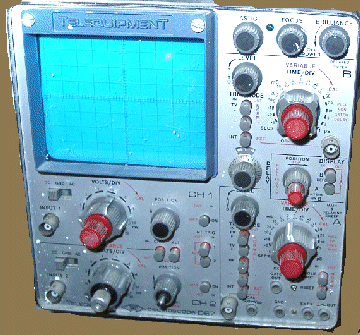
given data. Maths formula also most certain to be used in this question !!! The Oscilloscope This is a very useful piece of test equipment. A basic oscilloscope provides a means of measuring voltages AC and DC, from a few millivolts to tens of volts, and measurements of time intervals ( for AC wave waves ) from a few microseconds to seconds, SIMULTANEOUSLY! The scope will not have an infinite range of AC frequencies it can measure and unless it is a very expensive scope then the limit is likely to be a maximum of 100MHz. It is critical when using a scope to have a purpose made Scope Probe as shown in the diagram below.  The
scope probe should be rated at twice the maximum frequency
range that you might wish to measure and use the Earth tail
with croc clip to attach to Ground and the probe to connect
with the point to the measures..
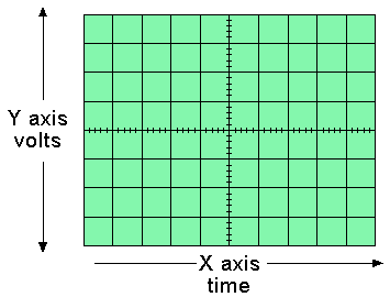
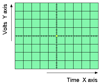
The information is displayed visually on a cathode ray tube ( CRT ) The diagram above shows the typical external and internal structure of a Cathode Ray Tube. Above is shown the calibration graticule on the tube face.
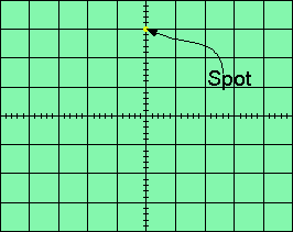
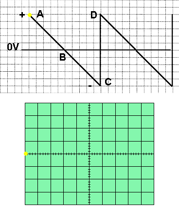
1. A CRT is a form of valve, with a heated cathode, a grid which controls the current flow, and a hollow anode at positive voltage ( several kV ) to accelerate electrons towards the tube face. 2. Another Anode focuses the electron beam to a fine point at the screen which is covered (internally) with a phosphor which glows ( green in most cases) when the focussed beam strikes the surface, it produces a bright spot (which should be in the centre with no applied voltage to the probe as shown below). 3. A pair of metal plates above and below the beam provides a means of bending the beam in the vertical plane ( Y deflection ), up if the upper plate is positive and the lower plate is negative and vice versa. The amount of the bend depends upon the potential difference applied. 4. A similar pair of plates, arranged left and right provides beam bending in the horizontal plane ( X deflection ). By adjusting the potentials on X and Y plates the spot may be positioned anywhere on the CRT display. 5. To provide an input to the scope, a coax lead with ground clip (outer) and probe(inner) is connected to an amplifier (Y amp) with the switched gain control, calibrate to move the spot so many cms per volt (so many divisions per volt), often from 10mV/cm to 10V/cm in 10 steps. So now we have a DC volt meter - if we set the Y amp switch to 1V/cm and apply +3volts to the input lead, the spot will move 3cm up the tube! 6. What if the input were a sine wave, 6V peak to peak? All we would see is a vertical line going 3cm up and 3 cm down not much use. Let's say that the sine wave is at mains frequency 50Hz. Each cycle will be 1/50th of a second or 20 milliseconds. 7. This is where the X ( horizontal) plates come into use. Within the oscilloscope, a variable frequency oscillator generates a SAWTOOTH wave form like that shown below. This is applied to the Left hand horizontal deflection plate.
Starting at A the plate is fully positive, the spot will be on the left hand side of the tube and will move in a linear manner towards the right. When at point B the plate is at zero volts, and when fully right at point C the plate is fully negative. At this point the spot on the screen flies back (FLYBACK!) to the left hand side, point A on the tube (almost instantaneously) and the charge on the plate moves to the point D on the sawtooth diagram, and the SWEEP repeats again and again.
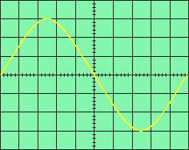
8. If we adjust the duration of the Sweep (TIMEBASE X plates) to 20 Milliseconds, and the sine wave in para 6 is still applied to the Y plates you will see the diagram below (assuming that the trace is what is called "locked" and not drift across the screen). As with the vertical input the horizontal input also has a gain control.
With time base of the scope set to 2 milliseconds per horizontal cm tells us that a whole cycle cycle is 10 x 2 = 20 mSec. The peak to peak voltage is still 3V AND we can see the wave form is sinusoidal. 9. Unless the sweep frequency is very accurate, it will not be synchronized with the sine wave and it will slowly drift one way or the other across the screen. By using the input sine wave form to trigger the start of the sweep waveform, the scope allows the sweep to be synchronized (SYNC) and the display will be steady. A control (LEVEL) is provided to SYNC the sweep from any point on the negative or positive edge of the input waveform. 10. To avoid seeing the spot flyback at the end of each sweep a BLANKING waveform cuts off the CRT current automatically. 11. SHIFT controls are provided :- A: Horizontal - to centre the timebase and align with the graticule B Vertical - to align the input waveform with the graticule and to take account of AC waveforms with a DC component, e.g ripple on a PSU output. 12. Input. A switch allows for DC input, AC input (if we want to see the DC ripple on a power supply without the DC component) and "Ground" to allow Zero TRACE calibration. 13. Single shot. It is necessary to stop the sweep and allow a non-repetitive input to actually trigger the sweep. For example, if we have a pulse or noise burst which occurs once with long regular intervals. To do this we set the Y timing to something sensible to display the pulse width. Set the sweep switch to "norm" - there is no trace now the sweep generator is waiting for an input pulse to start, as before we can select + or - trigger and adjust the level for a steady display. 14. Dual Trace Oscilloscope Effectively it has two independent traces with all functions previously discuss. It allows for comparison of voltages, waveforms and comparative timing (phases?) only expensive units have dual timebases. In an earlier part of the course you learned about a sine wave and this is where you will need to apply the knowledge.
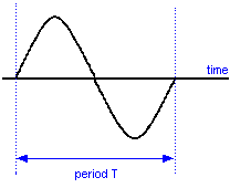
From the diagram first shown above :-
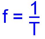
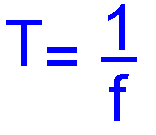
We know from above that f = 1 / T We know that t = 20 mSECS = 0.020 sec ------------------------------------------------------------------------------------------------------------------------------------------------------------------------------------------------------- Measuring DC Volts
|
|||||||||||||
|
|
|||||||||||||
|
|
|||||||||||||