|
Syllabus Sections:-
Measurements
9A7
56 Identify the circuit of an SWR
meter using either a sense wire between inner and outer
conductors of coaxial line or a current transformer and
capacitive voltage tap.
Standing Wave Ratio (SWR) meters
We have
found three different circuits for the SWR unit which at first
glance look very different but you should be able to see
similarities and thus be able to readily identify an SWR
circuit should it turn up in the exam.
Circuit 1
|
|
|

|
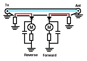
This is the first circuit note the diodes and two
meters and the two sections of red
coloured wire. The red
coloured wire is the sensing part of the
circuit as an incident signal passes down the
coax centre as shown in blue, the signal wire, it will
induce a signal in the sensing wire in an opposite
direction.
Whilst you might think that the right hand diode
would indicate the reverse signal you would be wrong
as it actually indicates the FORWARD SIGNAL.
With the wire
terminated in a resistor having a value of the
characteristic impedance ( 50Ω) the incident signal
will flow without REFLECTION. The diodes rectify the
incident and reflected signals and they
are displayed on the two meters as a forward
and a reverse reading. Only signals flowing in the
correct direction will be shown. So if there is no
reflected signal on dial will show zero and the
other the forward signal. When the incident signal
is not matched by the antenna then a reflected
signal will result and be displayed on the reverse
reading meter.
|
Circuit 2
|
|
|

|
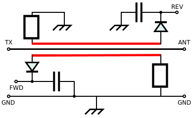
This is the second
circuit note particularly the two diodes and the
similarity with the circuit above.. As with the
circuit above there are two sensing wires indicated in
RED which again go under the braid in coax ( which is
not shown in this drawing).
In this diagram the location of the diodes is
different but the direction they are facing is
similar to the diagram above but here right hand
diode indicates the REVERSE SIGNAL and the left one
indicates the FORWARD SIGNAL. It is the direction of
current flow you need to appreciate.
The Forward and
Reverse meters would connect between GND and the
points marked FWD and REV.
|
Circuit 3
|
|
Take
a look at  page 98 Fig
14.8
|
This is the third
circuit note the use of a transformer CT and the
voltage is tapped off by C3. The braid is only
connected at one end but the unit must be in a metal
box to enclose the RF and thus prevent RF from
escaping ( through the screening box ).
|
STANDING WAVE NOTE
Standing
waves occur when a transmitter feeding a transmission line has
a load, or antenna, at the far end, not matched to the line
impedance.
The
Transmitter Voltage / Current ratio = the Line Impedance.
The
unmatched load cannot accept this ratio and some power is
reflected back towards the transmitter.
The
reflected current and voltage alternately ADD to and SUBTRACT
from the out going current and voltage resulting in points of
HIGH RF VOLTAGE and points of LOW VOLTAGE along the
transmission line which are NOT MOVING! (STANDING WAVES).
If we
could run an RF voltmeter along the transmission line we would
find points of HIGH Voltage and points of LOW Voltage at
regular intervals.
The ratio of high to low
voltage is the Standing Wave Ratio.
-------------------------------------------------------------------------------
9A7 56 continued Understand in
simple terms how this leads to an SWR reading on devices
using a single meter, twin meters or cross-needle twin
meter.
If you have a meter with
only one meter then there will need to be a change over switch
to change from Forward to Reverse SWR readings.
With a twin (two separate meters) meter unit one meter will show
you Forward and the other Meter Reverse SWR but this time
simultaneously reading can be seen.
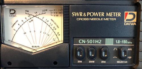
With a Cross-needle Twin
meter such as the one shown above. One needle arcs up from
bottom left the Forward reading needle and the other from the
bottom right the reverse reading needle. The meter is calibrated
to show forward and reverse AVG or PEP power according to the setting on
the selector button. The other three buttons are calibrated for
maximum deflection of respectively 20W, 200W and 2kW
forward power levels.
Additionally there is a group of marking called SWR rising at
changing angles from near the mid point where in the picture the
needles cross. When in use the Forward needle will rise
and also if there is any Reflected power the Reverse Needle will
rise. Where they cross you can then read off the relative SWR,
as approximated by the legend, on the meter.
The author of this web site has a preference for this type of
meter but also in the shack are single and dual meter SWR units.
|


