|
|||||||||||||
|
|
|
||||||||||||
|
|
|||||||||||||
|
Syllabus Sections:- Baluns 4B1 31 Recall the construction and use of transformer, sleeve and choke type baluns. Several names are given to baluns that tackle EMC problems.
Basically, a balun is a transformer. A one to one balun (1:1) transforms, for example, a 50 ohm balanced feed point on an aerial to 50 ohm unbalanced coax. With that in mind let's continue.
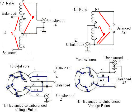
TRANSFORMER Let's look back at the principle of electromagnetic induction. You will recall that an alternating current flowing in the primary winding creates an alternating magnetic field, which in turn induces current in the secondary winding. Transformers are a major component in electrical and radio circuits, transferring or transforming voltages and currents up or down as required. In the diagrams below P indicates the Primary windings and S the secondary and it is to this that the equations relate. The circuits of 1:1 and 4:1 transformer baluns In a transformer the primary and secondary voltages are relative to one another or a ratio, i.e.- 240v primary & 12v secondary have a ratio of 20:1, the primary voltage is 20 times greater than the secondary voltage. The primary & secondary voltages maybe reversed but the ratio is still 20:1 or 1:20. The current ratio in a transformer is opposite to the voltage ratio, i.e. if the voltage steps up the current steps down & vice versa. For example; a transformer has a 240 volt primary @ 1 amp. The secondary voltage is 12volts provided the secondary winding can carry the current it has a potential of 20 amps because the ratio is 20:1 or 1:20. We have mentioned voltage and current but what about impedance transformation, impedance transformation is similar in that the load or secondary impedance might be 300O and the feed or primary impedance might be 75O the ratio is still 4:1 or 1:4 Let's look at the example. A transformer has a turns ratio of 1:2, in other words there are twice as many turns on the secondary winding than there is on the primary winding. It doesn't mater how many for the moment, but lets give it a figure of 1000 turns to 2000 turns, the turns ratio is still 1:2. The transformer has a secondary load of 16000 ohms or 16kohms, what is the primary impedance ??? Using the formula :- Zp = (Np / Ns)² x ZsWhere:-
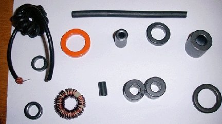
we can work out the primary impedance ? Zp = (1000 / 2000)² x 16000 ohms Zp = (0.5 )² x 16000 ohms Zp = 0.25 x 16000O = 4000 or 4k ohms Zp = 1000 ohms Zs = 4000 ohms Therefore the impedance ratio is 1:4 So as you can see the transformer has a turns ratio of 1:2 but has a impedance ratio of 1:4 or 4:1 depending on which way your looking. Try a few examples yourself; An antenna has a feed impedance of 300ohms, it has a matching transformer connected to it that has a turns ratio of 1:2, if the secondary of the transformer is connected to the antenna feed, what will be the input impedance?? Zp = (Np / Ns)² x Zs Zp = (1 / 2)² x 300 ohms Zp = 0.25 x 300 ohms Zp = 75 ohms Matching transformers or baluns (balanced to unbalanced) are often used as impedance matching devices the turns of wire being wound on a piece of ferrite or ferrite ring, ten double wound turns wound on a ferrite ring, the end of 1 winding joins together to form a centre tapped single winding, such a device gives an impedance transformation of 1:4 or 4:1, ideal for connecting to antenna systems as they will cover a wide range of frequencies. Examples of materials to make baluns and on the far left hand side examples of two baluns. By making taps on the balun different impedance transformations can be made. above is an example of a 4:1 balun. Ten turns of 1.25mm enamelled copper wire twisted together and wound on a t200 amidon ferrite core 2" dia. Twist together 1 end of 1 winding with the other of the second winding,to make a centre tap (identify which winding is which with a multimeter or put a bit of coloured tape on both ends of 1 winding before attaching to core). Tin the centre tap ends together. Tin the other two ends. The primary (unbalanced) is between the centre tap and one end. The secondary (balanced) is between end 1 and end 2. To test connect a 200 ohm carbon resistor load between end 1 and 2 (secondary). Connect your HF transmitter via an SWR bridge to end 1 and the centre tap. Transmit low power RF and check the SWR, it should be 1:1 or there abouts Above is a 1:1 balun wound in a similar way to the 4:1 except this time there are 3 windings so winding identification is all important. In the above example a smaller core (1.5") is used with slightly smaller (1mm) diameter enamelled copper wire but still ok for 100 watts or so. 1:1 baluns are often used for coupling feeder to antennas, or a choke balun wound using additional coax feeder and can be a cheaper option. Mount your balun in a waterproof plastic box (not metal) with suitable coax socket for input and a couple of 4mm insulated terminals for output. Remember baluns work best with resistive loads, if a reactive load is connected (high SWR, antenna too short or long for the band in use) they are not so efficient and can get hot, the heat is the power that is not being radiated. Other higher power examples Baluns can also be made using ferrite rod material, just coil the windings in the same way (just wind along the rod) and connect them up the same.
The Sleeve balun also known as the BAZOOKA Balun This
is a The Choke Balun The choke balun is where about 10 turns at a diameter of about 150mm coaxial line is formed into a coil at the antenna feed point. This is best used at lower HF frequencies as at higher frequencies it looses it effect of choking of the current flowing down the "OUTSIDE" of the feed line.
|
|||||||||||||
|
|
|||||||||||||
|
|
|||||||||||||
|
|
|||||||||||||