|
|||||||||||||
|
|
|
||||||||||||
|
|
|||||||||||||
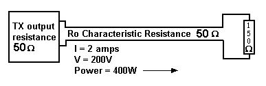
Before we go into the syllabus here is anexplanation of Standing Wave .We have added this section so that you can have a grasp of what STANDING WAVES are. Let's look at this from the point of view of the Transmitter (Tx). The Tx does not know what exists at the far end of the transmission line, so 200V/2A signal travels down the transmission line, building up an electromagnetic field, at a velocity close to that of light (for a good transmission line). The
signal then has an awkward situation to overcome when its wave
front arrives at the 150 The back pressure across the load rises above 200V and starts sending current back into the line, in opposition. The return current reduces the current flowing into the load, easing the situation. Looking
at the situation from the resistor load towards the Tx - there
is the same cable with Ro = 50 BUT how much current is going back ? Now for the maths - for those who only want the final resultant equations skip down to after ( Equation 3 ). So for those of you who are still with us here goes................ Let IR = Return current, and VR = Voltage needed to return that current. So from We have the initial Voltage V = 200 and initial Current I = 2 but as Ro is common to the initial V and I and VR and IR then stating it mathematically V + VR
MUST fulfill so The equations 1 and 2 are simultaneous and solving them gives us :- We should all be back together now !!! So back to our example From (
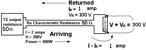
equation 3 ) again So the voltage across the load is V + VR = 300V And the current into the load is I - IR = 1 amp so AND Power arriving is 2 amps with pressure of 200 volts thus 2 x 200 = 400 watts Power returning (which we have just found out is 1 amp with pressure of 100 Volts) 1 x 100 = 100 watts 400 - 100
= 300 watts a purely resistive load For a line with a purely resistive load (i.e. load containing only resistance), SWR = R / Ro or Ro / R (whichever gives a value of 1 or greater). The SWR is directly related to the amount of mis-match between the characteristic resistance and the load. The higher the mis-match, the higher the SWR. For this example SWR = R / Ro = 250 / 50 = 5
Re-drawing the original diagram, with the new information added we have :- The reflected wave, current and voltage, alternately adds to and subtracts from the 2A/200V travelling from the Tx to the load. Starting with 1 amp / 300 volts at the load now move back a 1/4 wave towards the Tx, the original and reflected wave are a half wave apart (total journey to and from the load) and 1800 in phase - the two current are in phase, giving 3 amps and the voltages subtract giving 200V - 100V = 100V at a distance of 1/2 wavelength, phase difference is 3600 and we are back to the conditions at the load 1 amp /300V. At intermediate points there are different phases so the net current and voltages vary in a wave like manner (not a pure travelling sine wave) see the diagram below. The net current and voltage varies along the length of the transmission line. The high and low voltage points are in fixed positions. If the transmitter output is a pure sine wave, the forward and reflected waves are pure travelling sine waves. The forward and the reflected waves interact causing a resultant waveform which is a stationary wave called "STANDING WAVE". As mentioned above this standing wave is not a pure sine wave. So this static wave are not travelling waves like those causing them and can be measured by running a voltmeter along the transmission line. The standing wave ratio is 300:100 = 3:1 (max volts / min volts). NOTE:- At point X X a 1/4 wavelength back from the
load, the resistance R = V / I = 100 / 3 = 33.3 If we cut
off the load resistance and 1/4 wave length of feeder line, we
could fit a 33.3 The cable is now acting as a 3:1 transformer as well as a transmission line !! To complete this section we will deal here with :- Quarter Wave Transformer In our example a load resistor of 3 x the characteristic resistance of the transmission lines 3 Ro at one end is transformed to Ro / 3 at the other. In case
you had forgotten the Tx in our case was 100 Multiply the end values together 3 Ro x Ro/3 = Ro2 THE SAME RESULT IS OBTAINED FOR ANY LOAD RESISTANCE. Let the resistance at one end = R to be transformed to R1 at the other end R1 x
R = Ro2 so required Ro = We use a quarter wavelength of line having a characteristic resistance equal to Example. to make a 2000 A quarter wave transformer always has a standing wave along it. To be correct we should be dealing in impedances as we cannot avoid reactances so the equation becomes :- Zo2 = ZIN X ZOUT and we will have more on this on another page Quarter Wave Stubs If we put what would be a DC short at the end of a Quarter Wavelength of transmission line, and apply the correct frequency to the OPEN end, there will be maximum current and zero volts at the shorted end. Moving back from the shorted end to the open end when we get to a 1/4 wave length back , there will be zero current and maximum volts, which indicates A VERY HIGH IMPEDANCE. We can attach this stub anywhere along a working transmission line, it will have no effect despite the fact that at DC is looks like a short. This stub is used to support transmission lines ( at one frequency only ). it can be shown that at lengths between 1/4 wave and the short the stub presents an inductive reactance, decreasing as we move towards the short. Similarly, an open circuit stub presents a capacitive reactance which decreases as the open end is approached. The two reactance stubs can be used to cancel out unwanted reactance in a system and are particularly applicable at microwave frequencies. In the original example, the resistance a 1/4 wavelength back from the load is 33.3 ohms. The 1/4 wavelength transforms the impedance from 300 ohms to 33.3 ohms, but the SWR stays the same. SWR = Ro / R = 100 / 33.3 = 3. |
|||||||||||||
|
|
|||||||||||||
|
|
|||||||||||||


 must be obeyed even though we
are dealing with aerial feeders.
must be obeyed even though we
are dealing with aerial feeders.